Standard Design Micrometers
For all of our standard micrometers

|
Fasten micrometer in a clamp, then test by putting a set of gauge blocks between two measuring faces. They are the first-class gauge blocks as following: 52..15; 7.7; 10.3; 12.9; 15.0; 17.6; 20.2; 22.8 and 25mm. In above ten positions, get ten error data between micrometer reading and actual distance between two measuring faces. The absolute data of the largest one is reading error of the micrometer.
|
|

Measuring Face

|
Interference fringes number of
spindle measuring face: s M=2 |
The flatness and parallelism of measuring faces are tested by optical flat. Because of roughness of measuring faces, after optical flat contact with measuring face of spindle or anvil, there are gaps between faces, thereby interference fringes and rings appear.At vertical direction to measuring faces, each interference fringe or ring represents 0.3um of flatness error. |

|
Interference fringes number of
anvil measuring faces: N=2 Interference fringes number of two measuring faces: K=M+N=2+2=4 Parallelism of two measuring faces: 4x0.3=1.2μm |
Parallelism error of measuring: face
To test parallelism of two measuring faces of micrometers with upper range under 100mm, by optical flat specified with 1/3 or 1/4 of screw pitch of micrometer spindle. In turns, put optical flat between two measuring faces, turn measuring
For micrometers with range over 100mm, autocollimator can
|

|
Interference fringes number of
anvil measuring faces: N=1 Parallelism of anvil measuring faces: 1x0.3=0.3μm |
Flatness error of measuring :faceTo testing flatness and parallelism of measuring faces by second-class optical flat, adjust the flat to make interference band or ring to the least, ot to make to be closed interferencering.
Interference bands or rings with same color should not appeared over two stripes. (Flatness of measuring faces: <0.6μm).
|
Micrometers |
|
|

|

|
Measuring force device:
Measuring force device is used to drive spindle and
Ratchet stop:
Normal micrometers have ractet stop.
|
Measuring Technology Information- Various Errors
Visual error
For reticles on sleeve and thimble are not in a same planeˈthere appears visual error when reading on thimble from different points Aˈ B and C. Therefore, line of sight perpendicular to reticles on the sleeve (Point B as shown in picture). If read from point A or C, there is reading error about 2 μm. So, line of sight must be attended when reading.

Position error
Distortion of frame should be taken into account when using large micrometers. During measuring, ensure direction of measuring coincident with that of setting.

Temperature error
Infection of temperature should be taken into account when using large micrometers. For 1 meter long workpiece made of steel (as gauge block), there is error about 11 μm as temperature changing one degree. Because of different material of gauge block and micrometers, when temperature change similarly, change of their length are different. Therefore, when calibrating, keep micrometers and workpiece in place with stable temperature for enough time (3 hours) and keep temperature within [(20±2°C)].
Airy points
Airy points, supposition of optimal curving points to support boday of setting standard or tubular inside micrometer in level.
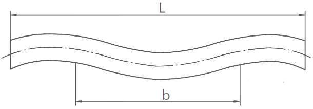
Airy points, supposition supporting two points, enable two sides surfaces parallel.
b=0.5577L
Abbe principium
Abbe principium Abbe principium says: “Only when datum lines of measuring system and measured workpiece are on a same line, measurement is most accuracy.” As drawing shows, when there is distance (h) between measuring faces and reading axis line, there will be measuring error ( ). Therefore, measuring force must be taken into accounted during such measurement.
ε = b-a = h tan θ

