I. Introduction:
1. General information
Hardness is an important parameter for mechanical performances of metallic and alloy materials. Generally, it refers to the capacity of a kind of material whose surface is penetrated by the other kind of harder material which has certain form and dimensions, and doesn’t produce residual deformation by itself.
Rockwell hardness test is the rapidest, easiest and most economic testing method in mechanical performance tests. Featuring high efficiency and easy-to-operate, the hardness values can be obtained directly. In most cases, it can fulfill the work that other mechanical performance test fails.
Accusize Rockwell Hardness Tester, item #RT90-0330 won the silver medal of the State Superior Product for three consecutive sessions. It is widely used to measure the Rockwell hardness of hard alloy, quenched and unquenched steels in the labs of research institutions, colleges, factories and mines.
2. Principle of Test
Rockwell hardness test is to apply diamond cone indenter (see Fig-2) or steel ball indenter (see Fig-3) to the specimen surface in two steps as shown in Fig-1, which shall be retained for a certain period of time, and measure the residual indentation depth under preliminary test force after the main test force is removed. The Rockwell hardness is calculated by formula (1) as per the h value, the constant N and S (see Table 1).
Rockwell hardness value = N-h/S …………………… (1)
Table 1 Symbols and Descriptions
|
Symbols |
Descriptions |
Units |
|
F0 |
Preliminary test force |
N |
|
F1 |
Main test force |
N |
|
F |
Total test force |
N |
|
S |
Unit of given scale |
mm |
|
N |
Hardness value of given scale |
|
|
h |
Residual indentation depth under preliminary
|
|
|
HRA |
Rockwell hardness = 100-h/0.002 |
|
|
HRC |
||
|
HRB |
Rockwell hardness = 130-h/0.002 |

Fig-1 Principle of Rockwell Hardness Test
In Fig-1:
1-----Indention depth under preliminary test force F0;
2-----Indention depth under main test force F1;
3-----Depth of elastic come-back after main test force F1 is removed;
4-----Residual indention depth h;
5-----Specimen surface;
6-----Measurement datum plane;
7-----Position of indenter.
Example: 59 HRC indicates that Rockwell hardness is 59 measured by C scale.
3. Range of Application
As per hardness range and size of the specimen, different indenters and loads can be selected and the hardness values can be indicated by different scales such as A, B and C scales for Rockwell hardness. The loads, indenters, values of the constant K and ranges of application are shown in Table 2.
- Scale A is used to measure the metallic materials whose hardness exceeds 67HRC, such as tungsten carbide, hard alloy, hard thin slabs and surface hardened parts. The range of measurement is 20—85HRA.
- Scale B is used to measure the lower-hardness parts whose range of hardness shall be 25—100 HRB, such as non-ferrous metal and its alloy, annealed steel, etc. If the hardness of specimen is smaller than 25HRB, the metal will begin to creep, the creep deformation will last a long time and the result will be inaccurate. If the hardness of specimen is larger than 100HRB, error will happen since the steel ball indenter is prone to deform and the depth of indention is too small.
- Scale C is used for hardness test of specimens which are quenched or tempered, such as carbide steel, tool steel and alloyed steel. The range of measurement shall be 20—67 HRC. If the hardness of specimen is lower than 20HRC, the measurement is incorrect since it is too deep for the diamond indenter to penetrate into the specimen and the error will increase caused by the geometric shape of the indenter. If the hardness of specimen is larger than 67HRC, the diamond is easy to damage due to the large pressure produced by the sharp tip of the indenter.
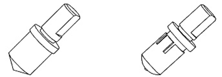
Fig-2 Diamond cone indenter Fig-3 Steel ball indenter
Table 2 Usual scale for Rockwell Hardness
|
Scale |
Indenter (mm) |
Test force (kg) | Constant |
Application examples |
||
|
F0 |
F1 |
F |
N |
|||
| A | Diamond cone indenter |
10 |
50 |
60 |
100 |
Hard metal and alloy |
| B | Steel ball(∮1.588) indenter |
10 |
90 |
100 |
130 |
Non-ferrous and soft metal |
| C | Diamond cone indenter |
10 |
140 |
150 |
100 |
Structural and tool steel |
4. Technical Parameters
Main technical parameters are listed in Table 3 and Fig-4.
Table 3 Main Technical Parameters
| Items(Code) | Contents |
| Height (H) | 630mm |
| Width (W) | 238mm |
| Length (L) | 466mm |
| Max. height of specimen with protection sleeve (B) | 100mm |
| Max. height of specimen without protection sleeve (B) | 170mm |
| Distance between the center of indenter and wall of machine (A) | 135mm |
| Net weight of hardness tester #RT90-0330 | 65kg |


Fig-4 Schematic Diagram of Overall Dimensions
| Scale | Range of hardness | Readings allowance |
|
A |
20HRA<~≤75HRA | ±2HRA |
| 75HRA<~≤88HRA | ±1.5HRA | |
|
B |
20HRB<~≤45HRB | ±4HRB |
| 45HRB<~≤80HRB | ±3HRB | |
| 80HRB<~≤100HRB | ±2HRB | |
| C | 20HRC<~≤70HRC | ±1.5HRC |
5. Descriptions of Mechanism Parts
The tester #RT90-0330 is composed of machine body (1), indenter (21), loading and unloading
mechanism (2, 20), measurement mechanism (23), load changeover mechanism (24),
specimen support mechanism (5), buffer mechanism (19) and so on (see Fig-5).

Fig-5 Schematic diagram of parts
1. machine body 2. loading handle 3. elevation handle 4. hand wheel
5. elevating screw rod sleeve (elevating screw rod inside) 6. specimen to be tested
7. main shaft 8. smaller lever 9. larger lever 10. adjustment block
11. position mark 12. hoist ring 13. screw 14. weight changeover support bracket
15. weight 16. oil needle 17. oil carpet 18. rear cover 19. buffer
20. unloading handle 21. indenter 22. top cover 23. indication dial gauge
24. load changeover handle 25. worktable
The test force applied onto the main shaft is amplified by the composition of weights and lever, i.e., indenter penetrates into the specimen surface under the guidance of buffer with the load amplified by the larger lever. At the same time when the indenter presses into the specimen, the vertical displacement produced by the main shaft is transmitted to the reading device through the measurement lever and hardness value is indicated therein.
- The machine body is the shell of the tester, where other parts are fitted directly or indirectly onto the machine body. Except the worktable (25), elevating screw rod (5) and operation handle, all the other mechanisms are fitted inside the shell, convenient for cleaning.
- The total test force is composed of main test force plus preliminary test force. The preliminary test force is produced by the weight of parts including larger lever (9), and main shaft (7). The weights (15) are hanged on the larger lever through hoist ring (12), producing main test force by the lever principle.
- The top end-face of indenter (21) bears the total test force and the sharp tip penetrates into the surface of the object to be tested.
- The load changeover handle (24) can be turned to different positions, which simultaneously regulates the positions of weight changeover support bracket (14), resulting in different composition of weights which makes up three different total test forces such as 588N/60kg, 980N/100kg and 1470N/150kg.
- The loading handle (2) is to apply main test force.
- The unloading handle (20) can be pushed back as per the direction shown on the label, removing the main test force. The application of main test force can be kept at certain speed by regulating the oil needle (16) of buffer (19), avoiding any impact.
- Test value can be read directly from the indication dial gauge (23) of measurement mechanism.
- The specimen support mechanism including worktable (25), elevating screw rod (5) and hand wheel (4) is used for bearing hardness blocks and the parts to be tested.
